
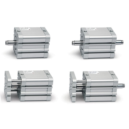
Compact cylinders ISO 21287 Series 32
Single and double-acting, non-rotating, auto-cushioned
ø 12, 16, 20, 25, 32, 40, 50, 63, 80, 100, 125 mm
Series 32 cylinders, thanks to their compactness, are suitable for installation in confined spaces.
Being in compliance with the ISO 21287 Standard, the cylinders Series 32 can be used in conjunction with mountings/accessories suitable with ISO 15552 standard.
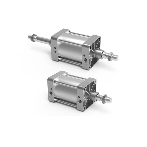
Cylinders Series 40K
Double acting, cushioned, magnetic
Ø 160 - 200 - 250 - 320 mm
Series 40K cylinders comply with the ISO 15552 standard and can be assembled with the entire range of standard accessories.
A permanent magnet on the piston of these cylinders is able to send, through proximity switches mounted on the cylinder sliding axis, electrical signals to indicate its position.This series is normally equipped with end-stroke cushioning which can be adjusted through a screw on the end block.
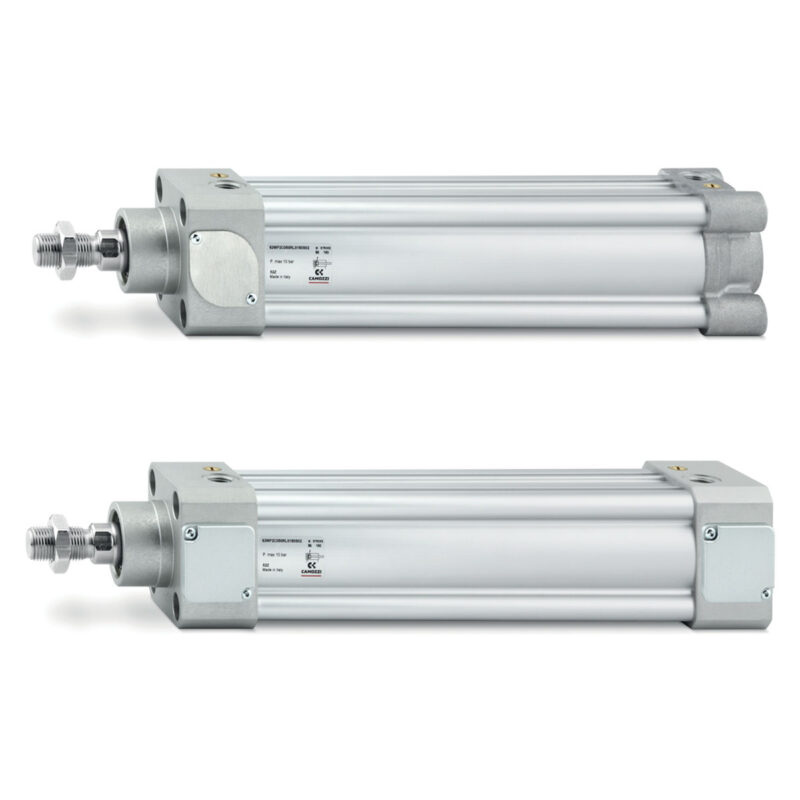
END LOCK cylinders Series 63
Double-acting, magnetic, cushioned ø 32, 40, 50, 63, 80, 100, 125 mm
END LOCK pneumatic cylinders are fitted with automatic mechanical end stroke locks which guarantee safe and secure holding of the cylinder rod in both the fully retracted and fully extended positions.
The locks activate and release automatically, without the need for external signals or commands and cylinder END LOCK Series 63 comply with ISO 15552.
The automatic mechanical lock therefore makes the END LOCK cylinders Series 63 highly suitable for use in sectors and for applications where it is essential to lock the cylinder’s position, both to avoid sliding during long stops and in situations with an absence of air, for example in transportation, printing & paper and the woodworking industry.
In addition, their capability to withstand external forces, that are much higher than the force exerted by the piston, makes the END LOCK cylinder the ideal solution for applications such as lifters, positioners and presses where a greater degree of safety is required compared to the more traditional rod locks combined with blocking valves.
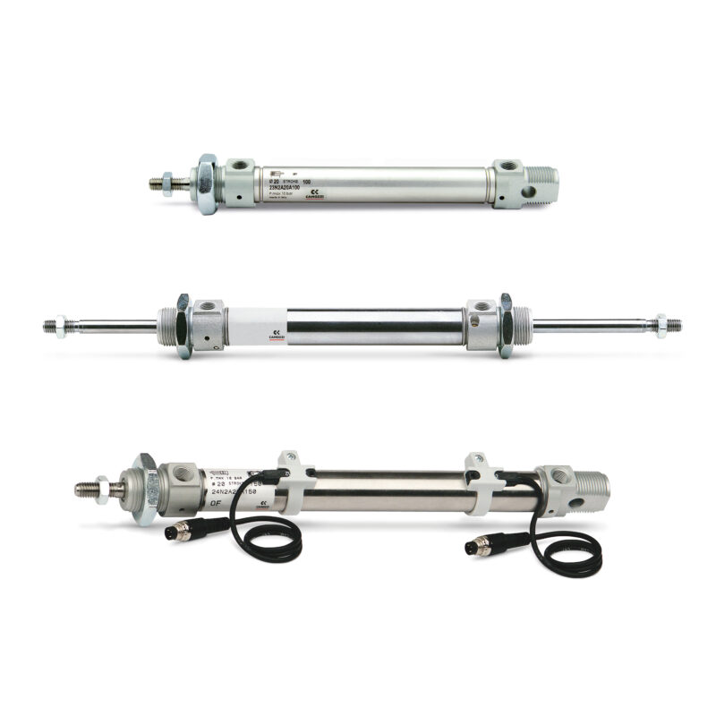
Series 16, 23, 24 and 25
Series 16: Ø 8, 10, 12 mm - non-magnetic
Series 23: Ø 16, 20, 25 mm - magnetic, auto-cushioned
Series 24: Ø 10, 12, 16, 20, 25, 32 mm - magnetic
Series 25: Ø 16, 20, 25, 32 mm - magnetic, cushioned
Series 16, 23, 24 and 25 mini-cylinders are designed according to ISO 6432. It is possible to choose from three different types of cushioning: mechanical (standard bumper on Series 16 and 24), adjustable pneumatic cushioning (Series 25) and pneumatic auto-cushioning (Series 23).
This last version, thanks to a patented system, automatically adjusts the cushioning in order to provide optimal deceleration during the entire cushioning phase.
The cylinder enjoys smooth, jolt-free movement, reducing vibrations and noise, while also guaranteeing high reliability and constant performance over time.
The adopted technical solutions and the choice of materials have provided the basis for a complete range of versatile and very reliable mini-cylinders.
They are suitable to be used in a multitude of industrial applications, especially where operating conditions undergo changes over time like for example wear of machine components.
Various mounting accessories are available to fix the cylinders in different ways.
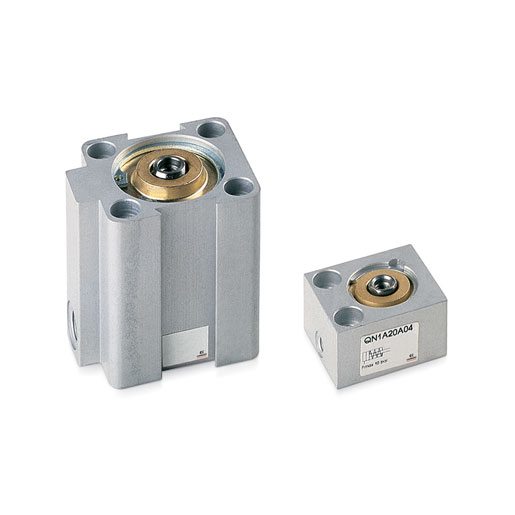
Short-stroke cylinders Series QN
Single-acting, non magnetic
ø 8, 12, 20, 32, 50, 63 mm
Series QN single-acting short-stroke cylinders have been designed so that they can be installed in very small spaces.
Due to the compactness and sturdiness of these cylinders, they are mainly suitable for positioning and locking.The available strokes are indicated in the tables.